The model originally purchased as unpowered can be converted to a powered one later by purchasing and installing the power package. The construction of the pod is carbon fiber/Kevlar composite, specifically a solid laminate (no core) of two plies 5 oz carbon fiber with two to four Kevlar plies sandwiched in between. This material is chosen as best for its toughness and high impact resistance, The target weight is 20-25 lb, 45-50 lb for the powered model.
The first prototype will be built as a proof of concept using only plain fiberglass laying up the shells directly over the foam plug. After the proof of concept is verified and changes if needed made, the plug will be finished and used for making of the production molds
After the serial production is established in accordance with the Hang gliding community demand an ultralight sailplane will be designed using the same pod in The pod and boom configuration, however the all composite construction will be optimized and designed for "ready to fly" serial factory manufacturing.
Here is how it's done
10-05-05
1-14-05

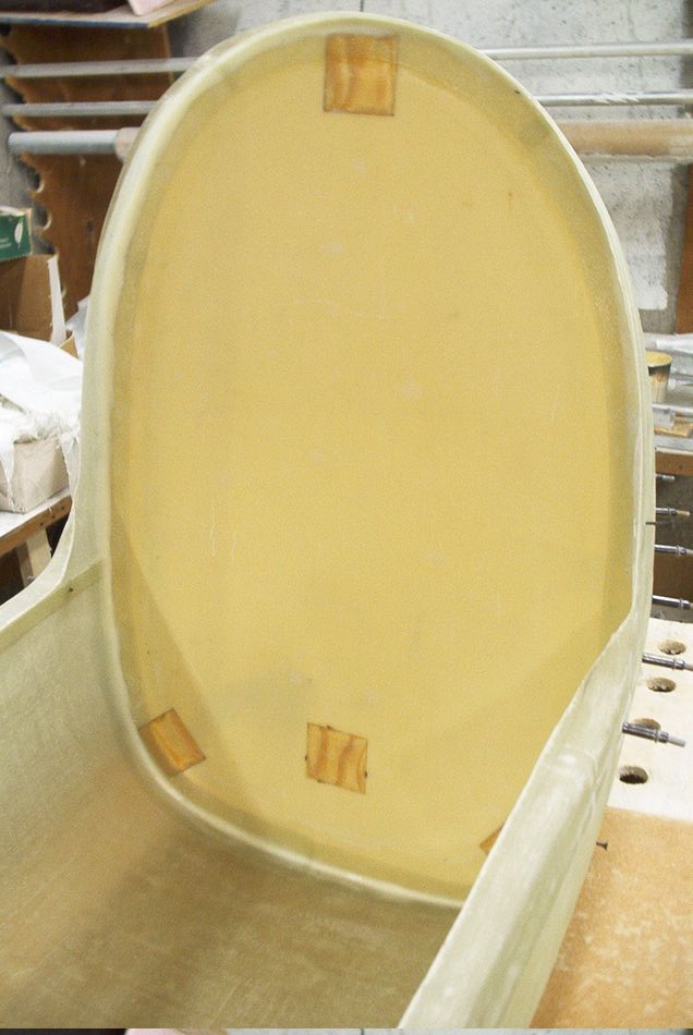
Starting with full size templates of the vertical and horizontal templates, these are transferred to the foam center reference ribs, the rest of the shape will be eyeballed from there. The engine is the position for the picture.
1-22-05
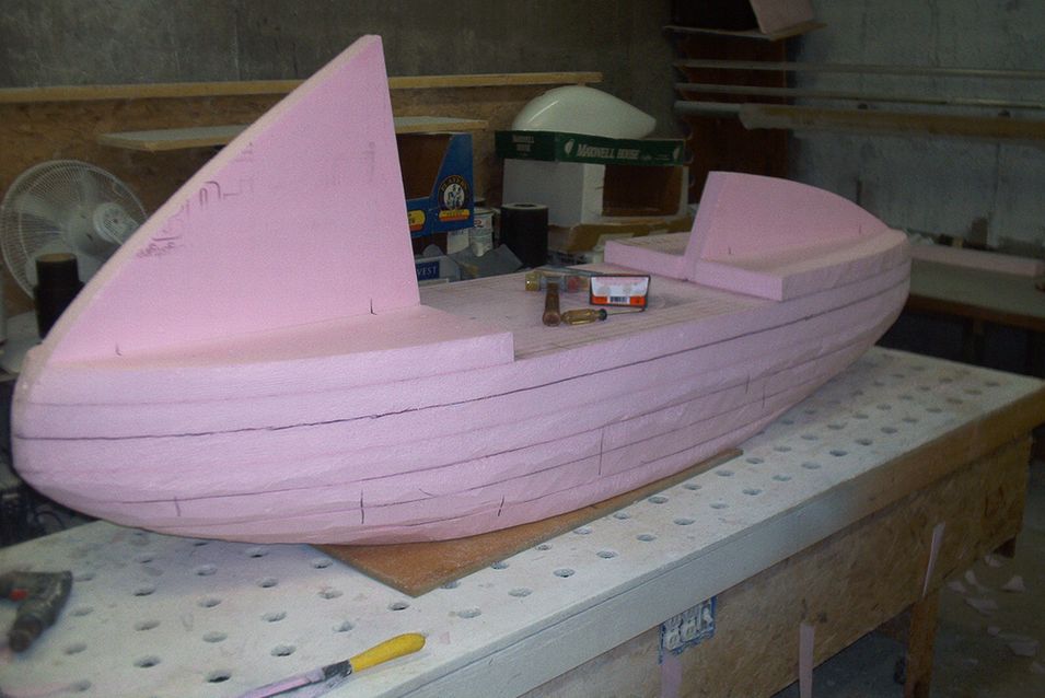
Gluing up the foam around the reference ribs with contact spray glue and with a help of 3 inch sheetrock screws to hold all together. .
1-25-05

The engine mounting cut out will be covered with an extra cowl like piece to completely cover the space on the unpowered model and cut out to clear the engine around as needed on the powered model.
1-26-05

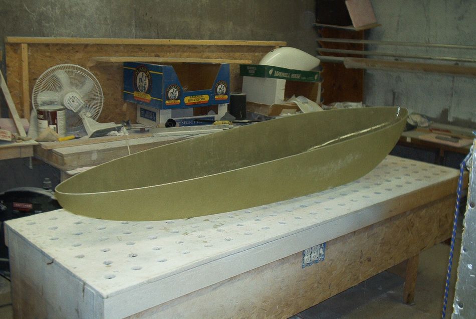
The finished shape, not 100% perfect but good enough to make the lay ups for the prototype proof of concept.
1-27-05
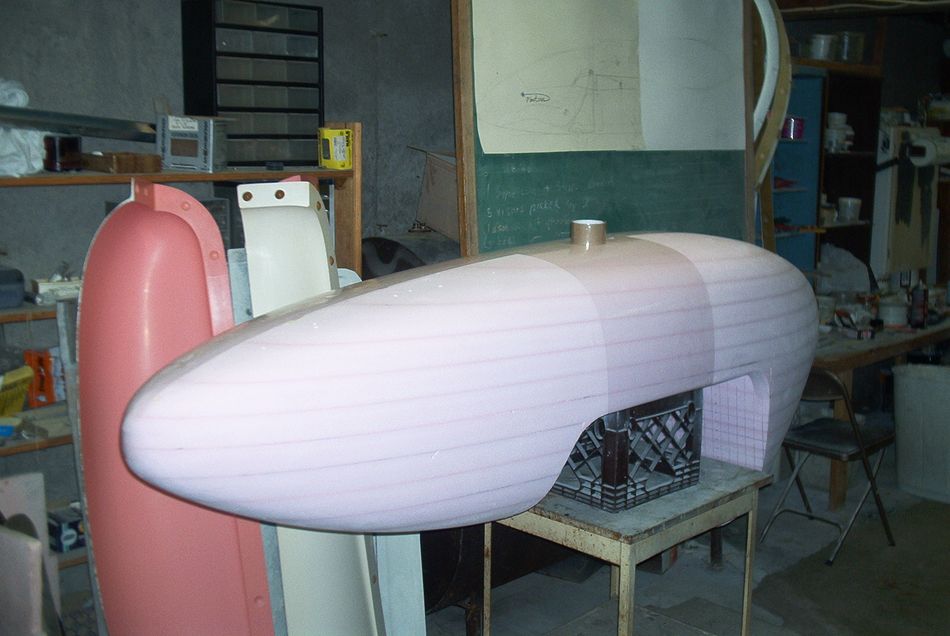
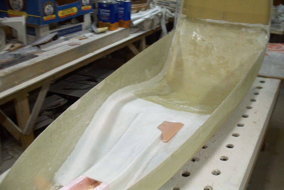
Aplying the release tape and getting ready for the lay-up, the bottom will be laid-up first.
1-28-05
The first lay-up, these are only 2 out of 4 plies needed, this is a tricky one with the sides going vertical and I can handle only 2 plies at a time.
1-29-05
Two more plies today and now it has to sit at least for two days to cure. The carpet on the floor got its share on resin on this one.
2-03-05
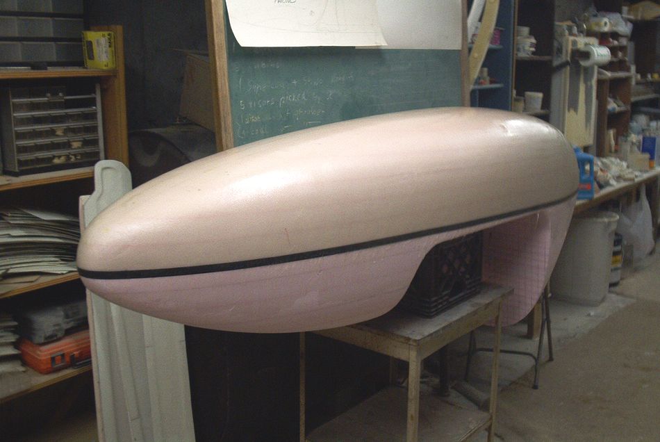
I finally pulled the part from the plug today , it came out great.
2-06-05

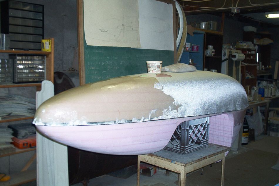
While everybody was watching Super Bowl and having a party I did the top half lay-ups , this should qualify as a mile stone of some sort because when I pull this off on Wednesday I will have a complete shell.
2-09-05

The top is off the plug, trimmed up and matched drilled to fit the bottom for holding it together with clecos. In case you wonder no, it doesn’t come off the plug easily, its an hour of wrestling by the end of which my arms are an inch longer from the pulling, there is blood from the cuts over the sharp fiberglass edges but at the end it comes off one way or the other.
2-09-05
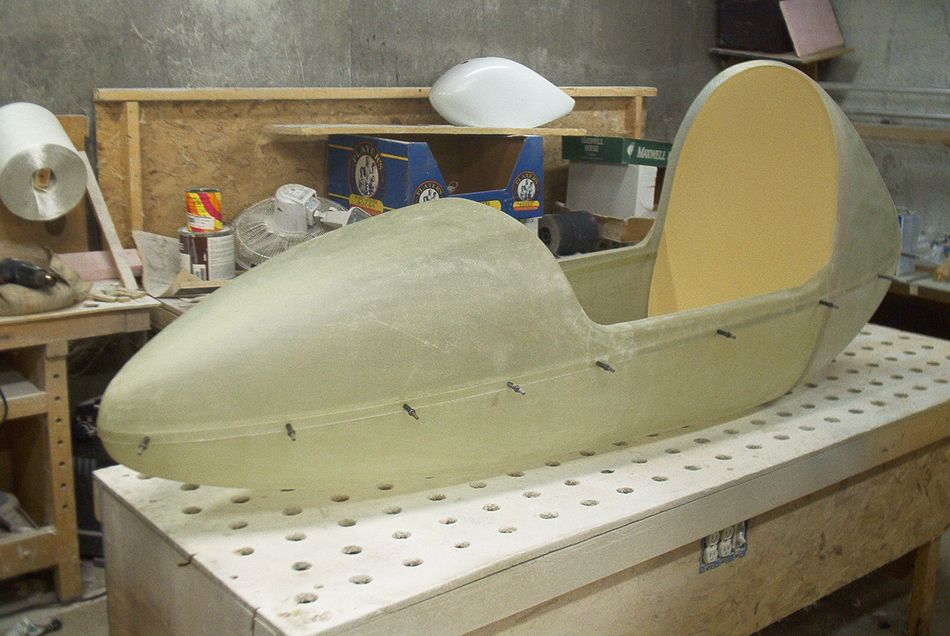
Fitting the main bulkhead, this is the main structural member that ties everything together, the bottom with the top , the seat pan and the hang point down to the main landing gear. It will be made from Ľ inch 6lb Last"A"Foam sandwich with some hard points built in.
Its good to be finally able to sit in it for the first time which is what I couldn’t do through the whole building process until now.
2-11-05
I laid up the bulkhead today, Two plies of 7781 on each side, the hard points for the landing gear are clearly visible here.
2-11-05
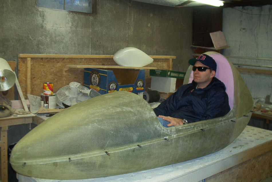
My chief Test pilot Tabor posing for the picture to give the perspective of the size of the pod, he is about 5’9" and 200lb. The actual dimensions of the pod are 92" tip to tip, 34" height, and 22" wide at the bulkhead.
2-12-05
The bulkhead is installed, bonded and taped. It’s actually bonded only to the bottom half, The tape in the top half is laid against release tape so it will form a flange for screws and the top half can still be removable.
2-18-05
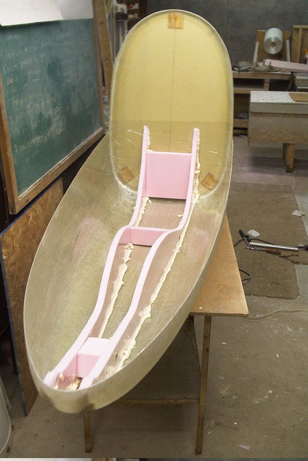
Working on the interior. There are two vertical ribs that run the length of the pod, in the rear they form a triangular brace between the bulkhead and the bottom pan and they stiffen the bulkhead in fore/aft plane. Up front the nose wheel will be mounted between the two vertical ribs and also the tow hook in the tip.
2-19-05
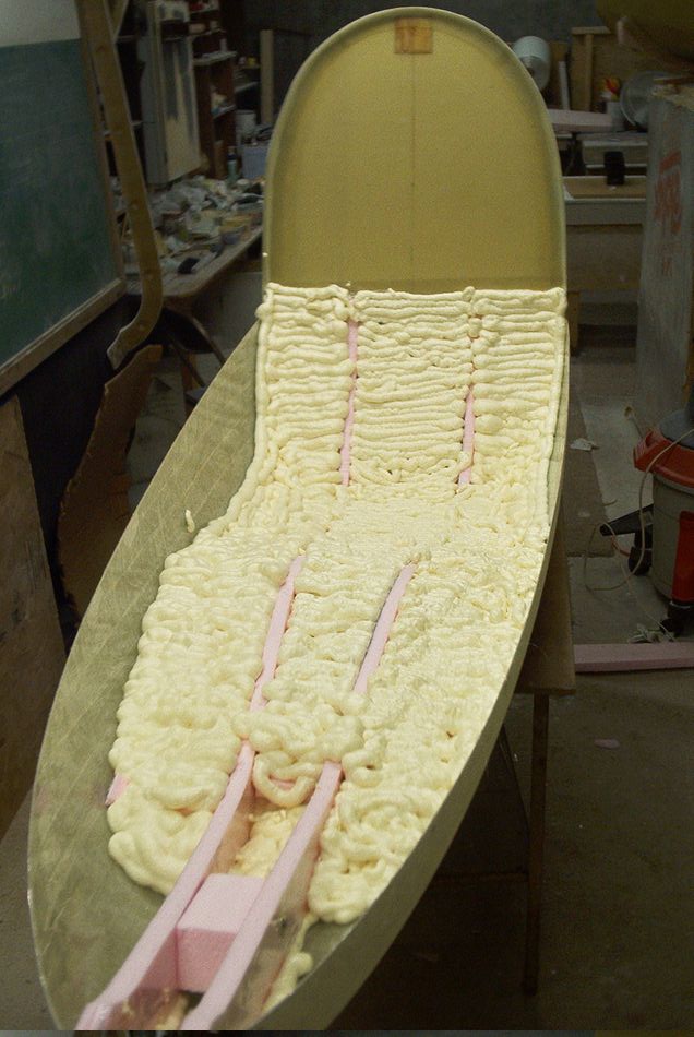
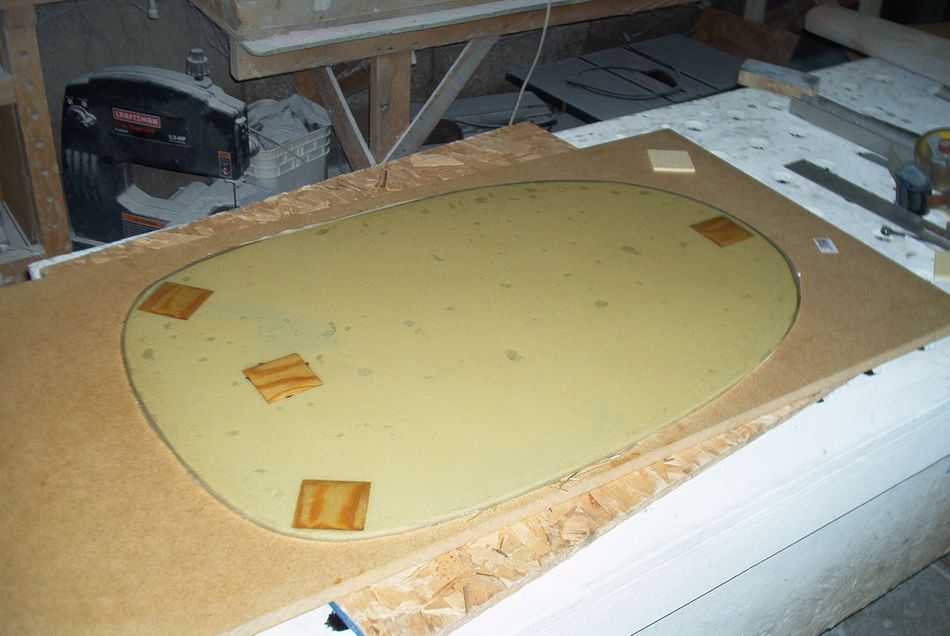
The foam is blown in for shaping the seat pan, after the seat is laid up the foam will be removed.
2-21-05
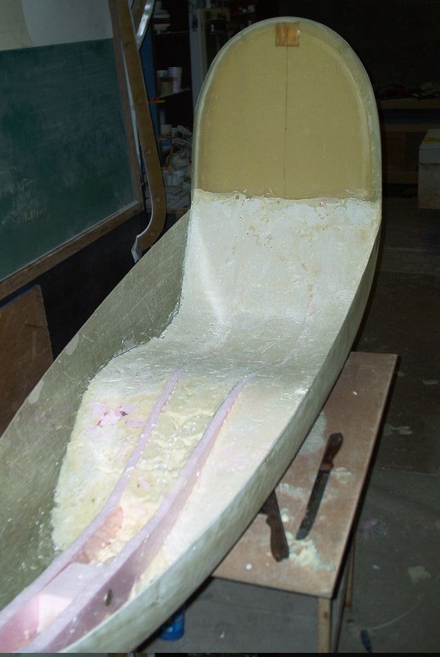
the foam is shaped and ready for the seat pan lay up.
I made a Hang Buggy group. I will be sending progress updates the same as they appear on the web page so if you join the group you will receive them automatically. The link is on the top of the page also.
2-22-05
My chief test pilot Tabor approved the final shape of the seat so I glassed the seat pan today.
2-27-05
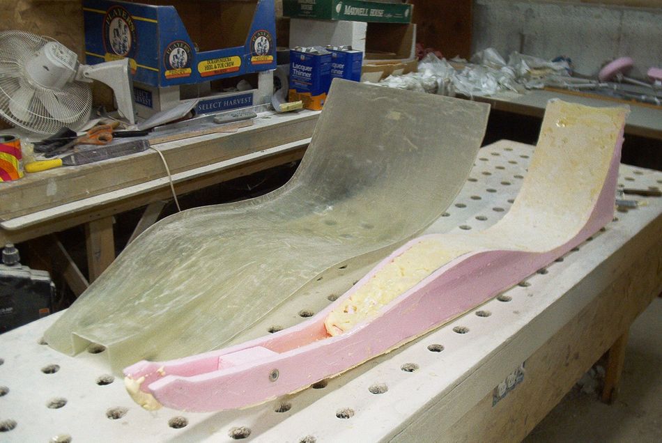
The seat pan is pulled and trimmed. The foam plug used to make it was constructed strategically in a way that the center part was preserved and will be reused one more time to lay up the vertical ribs against the sides with "C" shaped mating flanges.
3-20-05
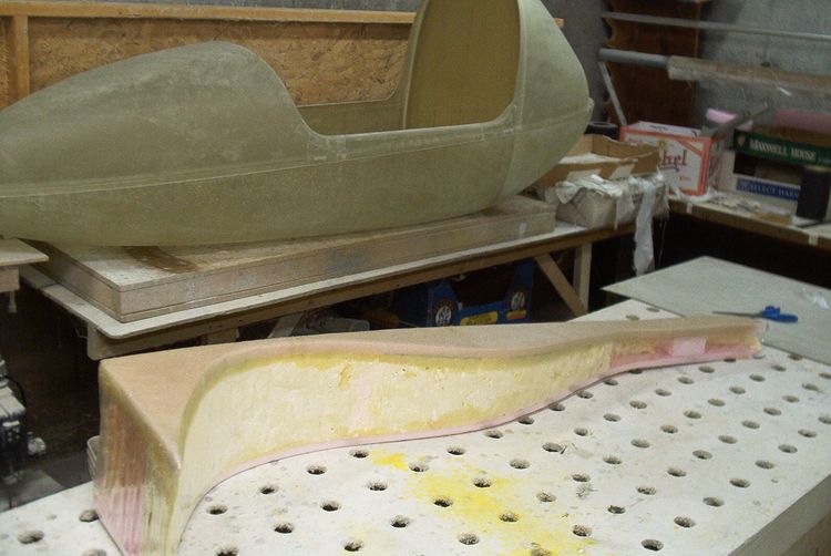
Laying up the vertical ribs after a little break. I was busy lately with making parts and fixing broken airplanes but a major development in the project was obtaining the glider wing. I now have a Falcon 195 glider to do the flight testing with.
3-21-05
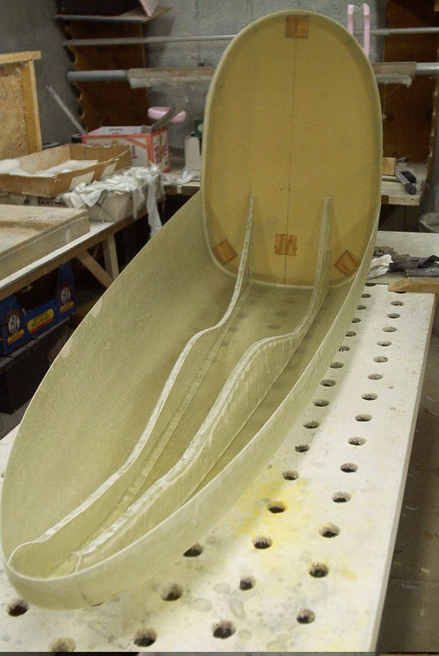
The vertical ribs are done and with this I reached another small milestone because all of the structural fiberglass body and internal components are finished.
7-11-05
The landing gear is installed and first down hill rolling tests were done, the gear work very well so far , the steering has good positive feel and tracking as confirmed by two other trike drivers, it has been load tested to 2G so far. Hooking to the glider is in progress.
The Hang buggy made its first public view at NH Greenland fly in.
7-26-05

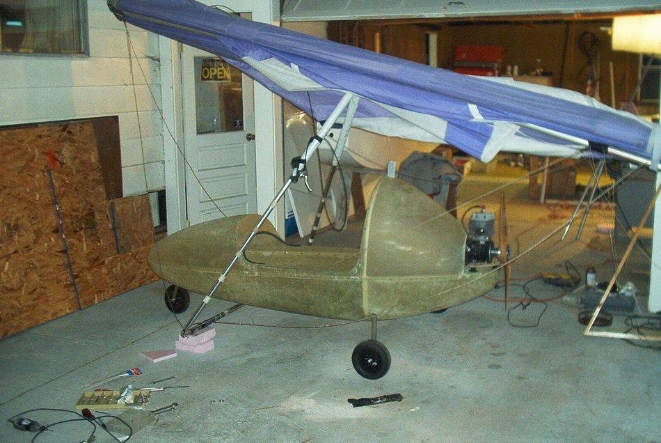
First glider hook in, these tubes are still pvc mock up. Everything seems to fit ok, rear wires are well clear off the prop, only minor adjustments are need for more push out and the landing gear needs to be raised a little, there is a provision for that. I fake painted the canopy on to show what the finished shape is supposed to look like.
8-25-05
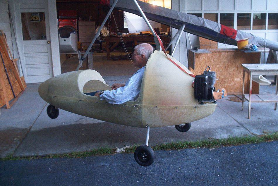
Hang check and dangle test with aluminum hang tubes finished. My Helper Ed acting as a crash test dummy, this turned out to be also a first drop test as when I trird to lower him down to the ground so can get easier out when I released the latch it just dropped at once from almost a foot height.
8-29-05

Here is Ed zipping along the runway doing ground testing.
First flights and preliminary conclusions
The complete body is made of only 6 structural parts, top, bottom, main bulkhead, two ribs, seat pan, plus one access door for a total of 7. There are about 25 additional mostly aluminum parts like gear tubes with their mounting brackets and hang tubes with their side plates, none of the parts requires machining, they are all stock angles, tubes bar and plate just cut off and drilled. There is one weld connecting the nose wheel fork to the pivot tube which are both 4130 steel.
I made three flights over the runway so far. My home runway is only about 1500 feet usable and very narrow with trees on sides, this is a bad mix when combined with my limited flying experience, I hade done one season of Hang gliding with about 70 flights from a 450 ft hill (Morningside) and this was 15 years ago, I had one 15 -20 minutes flight in a trainer trike just recently. Needless to say once airborne I was all over the place. I did quite a bit of taxiing and as I was getting comfortable with it I was pushing the speed higher and higher until it popped off the ground and I did a crow hop at about 6-7 feet height. I didn't intend to do crow hopping as I consider it too dangerous so in the next session I had the parachute installed plenty of gas and decided to go for it. The take off run was real short, it took only about 3 seconds to become airborne and the roll was about a hundred feet , It climbed to about 20 feet pretty quick and was pulling in quite a bit as I felt like I needed to keep the speed up . I proceeded climbing to a tree top level about 40-50 ft and at the point my climb rate went sour, I flew the rest of the runway length without gaining any more altitude so as the end got near I chopped the throttle and landed. I decided to go again but on the second landing I didn’t flare in time and hit hard bending the gear legs and splintering the prop tips. Next time when I get the new prop I will get an experience pilot to fly it to find out if the power is too low with this engine prop set up or if it was just me screwing up the flying.
The good part is that I learned everything I needed to know in building this prototype that I can proceed with making the production molds. The structural aspect and all the principles of the design are proving to work out well. The shape and the size of the prototype body is very close and only minor alterations will be done to the prototype plug and then it will be used to make the production molds. However this body style will be used only for the regular trike configuration which will hang below the control frame and will use bigger engine with redrive and a bigger prop , stronger wider landing gear, more fuel bigger wheels and so on. For the original hang buggy idea of the minimalist soaring pod flown inside the control frame a new smaller trimmed down body will be built on the same basic principle.
